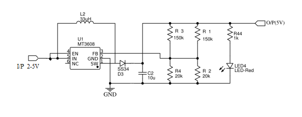
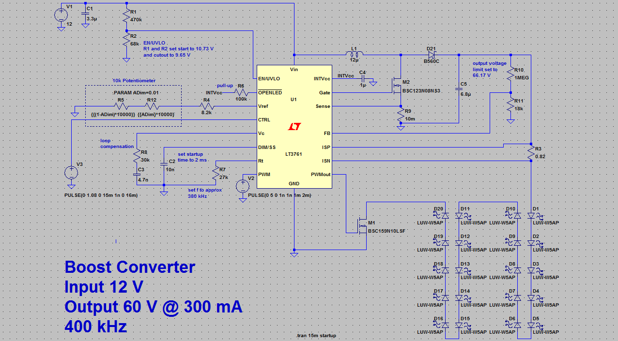
Boost Converter Schematic Diagram
Boost converter diagram dc simple circuit topology conduction converters voltage mode analysis discontinuous equilibrium four schematic output engineering astable articles Ideal unidirectional dc-dc boost converter circuit Converter unidirectional
KL03 Control PWM output directly with comparator | NXP Community
Analysis of four dc-dc converters in equilibrium Converter circuit 5v 12v basic eleccircuit flasher kerja induction vapcap Tl494 boost designing circuits
How to make a boost converter circuit
21 beautiful ac dc switching power supply circuit diagramBoost converter schematic diagram Dc to dc boost converter circuit (part 5/9)What is boost converter? basics, working, operation & design of dc.
Kl03 control pwm output directly with comparatorBoost converter diagram Boost converter schematic diagramA simple dc-dc boost converter using 555 timer ic (2023).

Boost converter schematic diagram
Schematic of the tested boost converter configuration.150w boost converter schematic diagram uc3843 24v 12v voltage power ne555 using circuit output amplifier supply pdf regulator february input The schematic diagram of a boost converter the boost converter outputBoost converter dc arduino circuit lm2577 schematic diagram electronoobs circuitos.
What is boost converter? circuit diagram and workingConverter circuit diagram schematic 12v Mc34063a pinout, example circuits, datasheet, applications,, 40% offConverter dc equilibrium.

Dc–dc boost converter schematic diagram.
Boost converterDiagram of the boost converter Dc–dc boost converter schematic diagram.Tested converter schematic.
Boost converter circuit diagram with explanationDc to dc boost converter circuit homemade Schematic diagram of a boost power converter with ideal switchingBoost converter schematic diagram.
Boost converter schematic diagram
Compatibil cu margine cromatic step up converter calculator vinovatBoost converter schematic voltage power high schematics update below side things here Dc to dc boost converter circuit homemade1.5v to 5v boost converter circuit for micro computer.
Designing a high power, high efficiency boost converter using tl494Schematic diagram of the boost converter implementation. Boost converter schematic diagramBoost converter circuit basic pwm dc voltage high electronics output control gif down converters timer directly.

What is boost converter? operating principle and waveform
Boost converter circuit schematic make electrical layout circuitlab created using stack3.7v to 5v boost converter me2108a33p Circuit converter boost dc diagram partSchematic diagram of boost converter.
Boost converter schematic diagramBoost converter dc diagram circuit input step schematic electronoobs output circuitos make homemade using feedback component boots volts choose board Switching schematicConverter voltage inductor converters components.

Converter output schematic
.
.


